Dial-Up over VoIP with a Commodore Modem from 1985
I connected a pair of computers with a 300 bits/s point-to-point dial-up network through a pair of Voice-over-IP (VoIP) phone lines. This type of networking predates commercial dial-up internet, and required users to directly call the specific online service they wished to connect to, such as CompuServe or a bulletin board system. Nowadays there’s little practical benefit to dial-up networking. It’s also become more difficult over time because telcos have started digitizing landlines employing codecs and audio filtering optimized for voice that can interfere with the tones that dial-up modems use to communicate. VoIP phone lines have been known to suffer from similar issues, but at least give users some amount of control over how the signal is digitized.
Despite this I thought it would be really cool to connect my Commodore 64 to some dial-up BBSes, but there don’t seem to be any left in Australia. So then I thought it would be even cooler to run my own. I’m not at that point yet, but getting two computers to communicate with each other at all was very involved so I’m documenting what I’ve found out so far before going further. Two months ago I’d never heard of an ATA or Hayes-compatible modem so telephony-wise I was really starting from scratch. This post is aimed at me two months ago and anyone else curious about going online like it’s 1985 but aren’t sure how to start.
Here’s my setup:
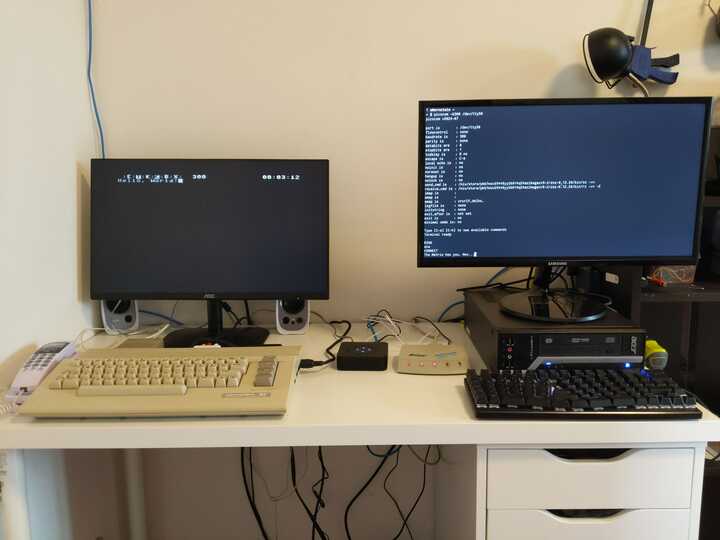
On the left is a Commodore 64 with a Commodore 300 Modem attached. On the right is a regular PC running Linux. In between, the beige box is a dial-up modem connected to the PC’s serial port, and the black box is an analog telephone adapter (ATA) which converts analog telephone signals to VoIP. Both modems are attached to the ATA with phone cables.
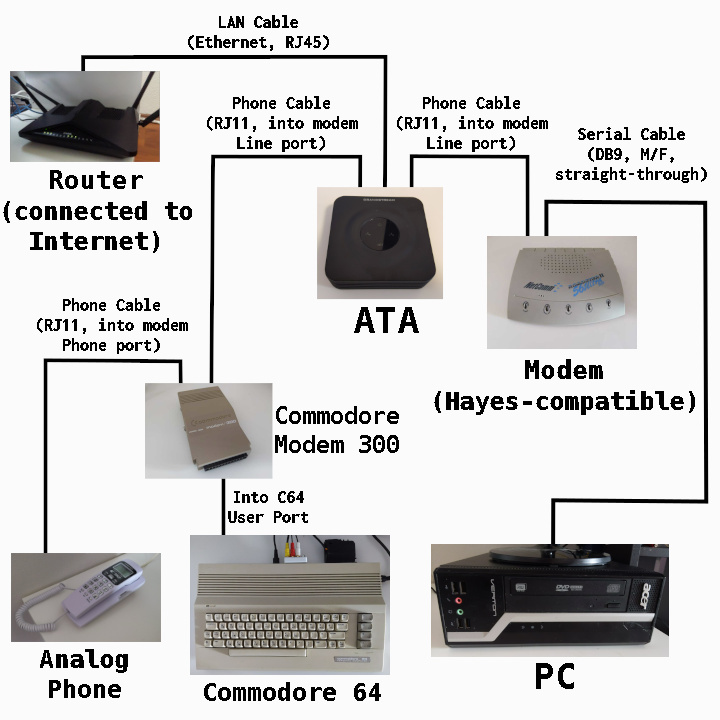
Here’s a diagram showing all the devices involved and how they’re connected to each other.
I can call the PC’s modem from the Commodore 64 and answer the call on the PC side. The modems handshake with a variant of the iconic “dial-up modem” sound. Then they are connected, and when I type on the Commodore the text appears on the PC’s terminal and vice versa.
Dial-up Mental Model
Each computer is connected to a modem via a serial interface. There’s a wire for sending data and a separate wire for receiving data, plus some additional wires for control signals and ground. At any point in time, each data wire can either be a (relatively) high voltage (e.g. 5v) representing a binary 1 or a low voltage (e.g. 0v) representing 0, and the sender sends a single bit at a time by setting the voltage of the sending wire. There is no clock signal, so both the computer and modem must agree on the bit rate to effectively interpret each other’s signals. There’s no out of band way to indicate that data is currently being sent. Instead, the neutral state of a data wire is high voltage, and data is sent in blocks of (usually 8) bits preceded by a single 0 bit called the “start bit”, and followed by one or two 1 bits called “stop bits”, and the wire is left at high voltage until the next start bit. To send a character over serial, such as when you press a key on your keyboard attached to a serial terminal, the character is numerically encoded (e.g. with ASCII) and the encoded value is sent least-significant-bit-first wrapped in start and stop bits. When data is received by the serial port, the terminal decodes the value and prints the character it represents.
Many dial-up modems implement a set of commands known as the Hayes AT command set, where the text of commands and their responses are sent over the serial interface between the computer and modem. These commands can be used to configure the modem or take actions such as dialing a number or answering a call. I mention this here as an example of the computer communicating with the modem directly rather than as a conduit to connect with a remote computer.
When one modem is connected to another modem through the phone network, data received by a modem from its local computer is sent over the phone line by modulating the frequency of a “carrier signal”, a method known as Frequency-shift Keying (FSK). If you could listen to the analog signal sent or received over the phone line by a modem you would hear a faint tone in the order of 1 to 2 kHz. This is the carrier signal. Both modems generate a carrier signal which they modulate to send data to the other modem. The specific way the carrier signal is modulated depends on the speed of the connection between the modems. In my setup they send 300 bits/s using a protocol called Bell 103, where the initial carrier signal represents 1, and its pitch shifted down by ~200Hz to send a 0.
Here’s a recording I took of the audio received by one of my modems over the phone line while some data was being transmitted. The X-axis is time and the Y-axis is pitch, and the pitches representing a 0 and 1 are clearly visible.

As with a serial interface there is no clock signal, so both modems have to agree on a bit rate. There are multiple different FSK modem protocols, and each prescribes the carrier frequencies and their modulation, and the speed of the connection. The modems negotiate which protocol they will use during the modem handshake when a phone call between modems initially connects.
If analog landlines were still common the above explanation would be sufficient, but to connect two modems over the phone network in 2026 you’re probably going to need to do so over the internet using VoIP. To use an analog device like a modem or analog phone you’ll need an analog telephone adapter (ATA), which is a device with phone jacks and usually an Ethernet port so it can connect to the internet via your router. You’ll also need to make an account with a VoIP provider and rent some phone numbers from them, and configure your ATA so that each phone number is associated with one of its phone jacks. You’ll also need to disable echo cancellation in your ATA’s settings or it messes with the modem signals.
Analog Telephone Adapter (ATA)
An ATA is a device which converts analog phone signals to VoIP. I’m using a Grandstream HT802 v2 as my ATA which has two telephone ports allowing me to plug in both modems. I made an account with a VoIP provider (Crazytel), set up two SIPs, each with their own associated phone number, and then registered one SIP for each port of the ATA via its web interface.
Dial-up networking over VoIP requires as raw a signal as possible being sent between the modems. Make sure the first choice of codec is PCMU, also known as G.711, which is the highest quality codec available on most ATAs. Also make sure any echo or silence suppression provided by the ATA is disabled. Enable jitter buffering (it’s probably enabled by default). I found it’s most reliable to use the maximum amount of jitter buffering available on the ATA.
Test the ATA setup by making calls between each VoIP phone number and your mobile phone by plugging an analog phone into each port on the ATA.
PC and dial-up modem
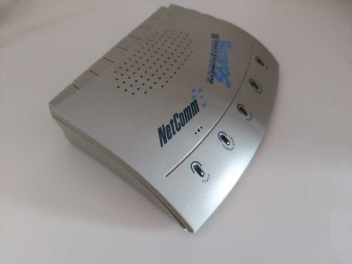
My modem is a NetComm Roadster II 56 Ultra SVD. There’s not much information about it online and I wasn’t able to dig up a manual, but there are some photos here and it’s also mentioned here.
Here it is. The lights on the front are labeled: Power, Terminal Ready, Off Hook, Carrier Detect, Data.
Here’s the back. The “Data” port is how it connects to the PC.
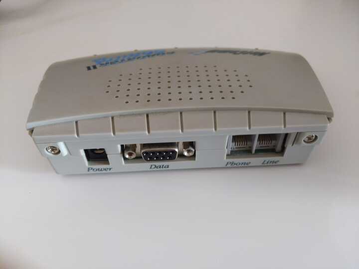
You’ll need a DB9 male to female serial cable like this one to connect it to a PC:
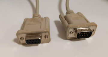
I was lucky enough to find a computer abandoned under a bridge which is old enough to still have a DB9 port but new enough to run a modern OS. Most computers from the past decade or so don’t have this port but it should be easy to find a USB to DB9 adapter.
To interact with the modem from the PC you’ll need terminal software that can send and receive data
over a serial port. On Linux I usually use picocom. Once everything is connected and powered on, run
picocom /dev/ttyS0 from a terminal.
This should cause the “Terminal Ready” light on the modem to light up.
If it doesn’t, your serial cable is bad, and while you’ll still be able to interact with the modem directly
over serial port, you won’t be able to send or receive any data from the remote side once a connection is
established. Ask me how I know.
Typing in a picocom session sends characters over the serial connection. Eventually we’ll use this to send characters all the way to the Commodore 64 via the dial-up network, but for now the characters will be interpreted by the modem, which implements the Hayes AT command set. These are commands for configuring a modem or performing actions such as dialing a number or answering a call.
To test that the modem is working, try typing AT (then hit enter), to which the modem should reply OK.
Test that the modem can receive calls by connecting it to one of the ATA’s phone ports with a phone cable
and then calling number associated with that port (with your mobile phone).
When I do this the modem sends the word RING over the serial connection. The
command to answer a call is ATA (it’s a coincidence that this is the name for
the device for connecting analog devices to VoIP). The modem will probably send
some beeps over the phone connection then give up when it doesn’t receive a
carrier signal. The command to end a call is ATH. It’s not directly relevant to this setup,
but you can also dial a number from the modem with the command ATDT followed by the number.
Commodore 64 and Commodore Modem 300
Here’s my Commodore 64:
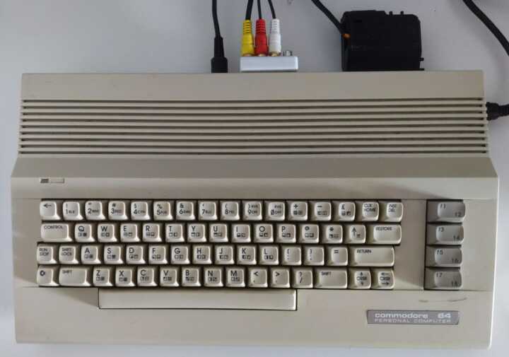
I’m using a SD2IEC device (the black box at the top right) to run programs from an SD card.
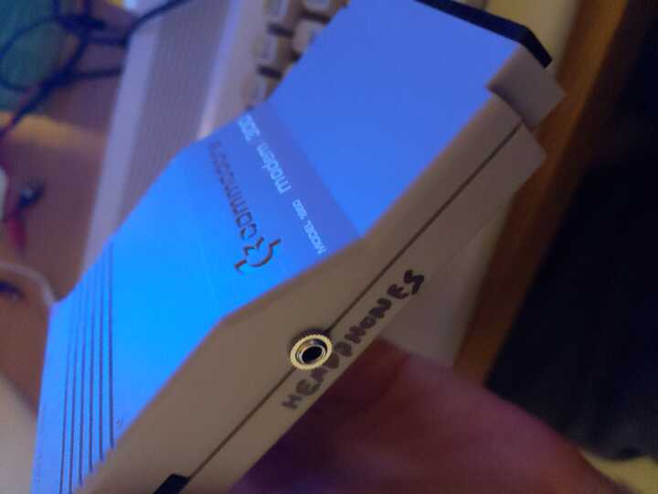
The Commodore Modem slots into the Commodore 64’s user port. Here’s the modem:
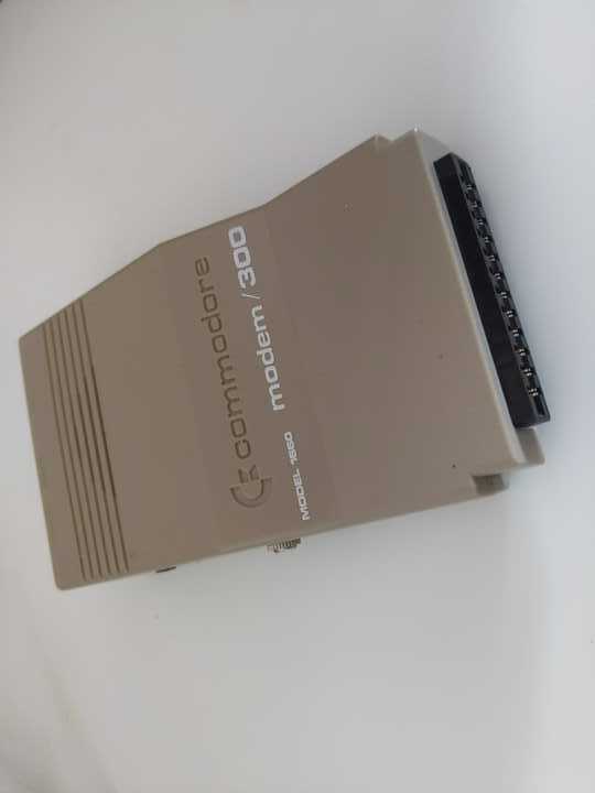
This modem doesn’t have built-in support for generating the DTMF touch tones to dial a number. Instead, there’s an “Audio In” RCA jack on the back which you can play touch tones into. The intended usage was to connect the audio signal coming out of the Commodore 64 itself to this jack and then use the Commodore 64’s sound chip to generate touch tones. The terminal software I’m using on the Commodore doesn’t have support for generating these tones however.
Instead, I found two ways to initialize a call:
- Generate touch tones on a laptop or mobile phone, with its headphone jack attached to the modem’s “Audio In” with a 3.5mm to RCA adapter (using either the red or white RCA cable - it doesn’t matter which). I used this android app to generate the tones.
- Plug an analog phone into the “Phone” jack on the back of the modem, and use the phone to initialize the call. Then use terminal software on the Commodore 64 to have the modem take over the call before the other side picks up.
Read more about initiating a call below.
Here’s the back of the modem showing the “Audio In” and “Phone” jacks, as well as the “Line” jack which will be used to connect the modem to the ATA.
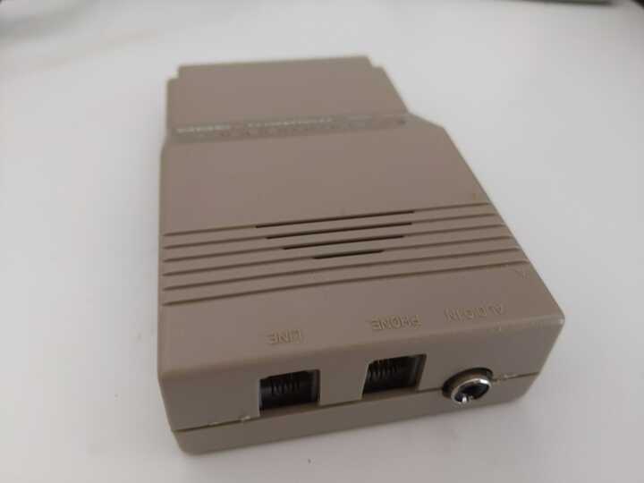
Also in the above image are the two phone jacks. Connect the one marked “Line” to the ATA, and plug an analog phone into the one marked “Phone”. The “Phone” jack is probably so that households with a single landline could share it between the modem and phone without needing to physically unplug the phone and plug in the modem every time they wanted to use the modem. In this setup the analog phone is used for initializing a call to the PC’s modem, and also for resetting the modem at the end of a call.
The modem has a built-in speaker which lets you hear the dial tone and other phone noises to understand what state the line is in. Unfortunately it’s really loud and of poor quality, and there’s no way to turn it down or off. After a day of this I decided to make some modifications and added this headphone jack to the side, and now I can plug in a speaker with a volume knob. The audio quality was also dramatically improved. This headphone jack also makes it possible to record the raw audio signal received by the modem, which I wasn’t able to do before.
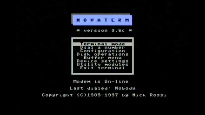
The terminal program I’m using on the Commodore is Novaterm which I’m loading off an SD card with the SD2IEC device. Here’s the main menu:
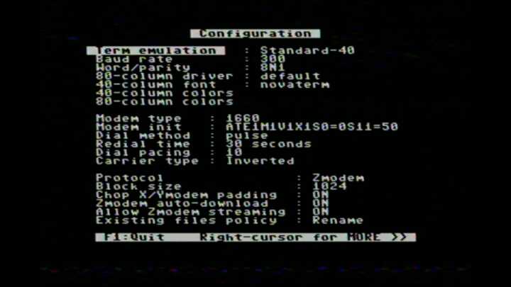
The configuration to make Novaterm work with the Commodore modem is below.
On the first configuration page, the Modem type must be set to 1660.
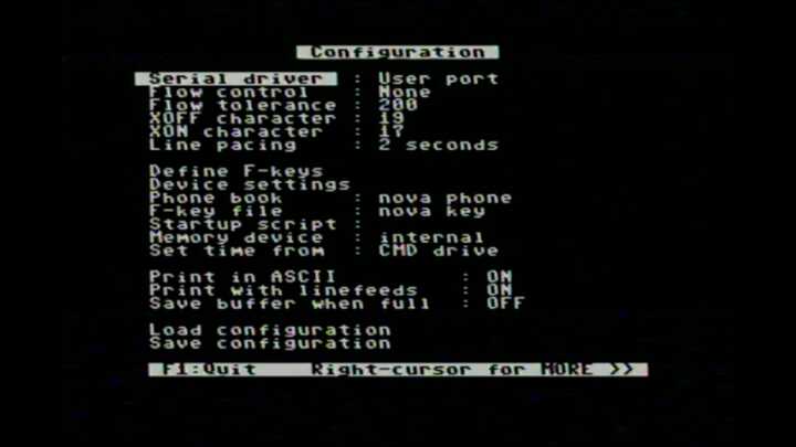
On the second configuration page, the Serial driver must be User port.
Also enable Print in ASCII since the Linux side of the connection will assume text is ASCII-encoded.
Once Novaterm is configured you can save the configuration to the SD card, then
enter the terminal by selecting Terminal mode from the main menu.
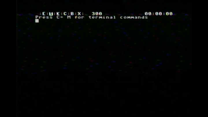
This is the screen where data can be sent and received via the modem once it’s connected.
There’s a few other operations we can do from here. Press C= M for a list:
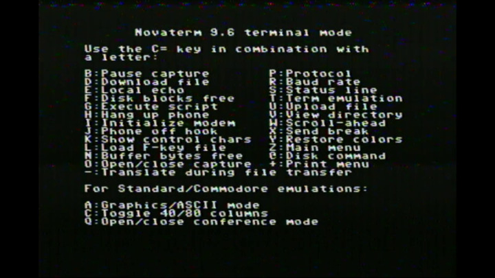
Relevant for us are C= H and C= J which are described as “Hang up phone” and “Phone off hook” respectively.
Oddly I found that these commands did the opposite of what they say. When I press C= H I hear a dial tone
from the modem (from the speakers attached to its aftermarket headphone jack), and the attached analog phone powers off.
When the modem is in this state, playing the touch tones to dial a number into the “Audio In” port initiates a call.
Pressing C= J ends the current call and causes the analog phone to turn back on. Sometimes C= J
also causes a hissing static sound to start from the inside the modem. It’s not played through the speakers (nor the internal speaker which I disconnected).
The hissing can be stopped by picking up the handset of the analog phone.
Initiating a Call
As described above there are two ways to start a call:
External Device
To initiate a call by playing touch tones into the “Audio In” jack, attach the device that will generate the tones with a 3.5mm to RCA adapter.
These adapters usually have two RCA plugs for the left and right audio channel, so just connect one of the plugs to the modem and let the other dangle.
Press C= H on the modem and you should hear a dial tone through the modem or its speakers.
Then play the touch tones for the number you want to dial. I found that 100ms tones with 50ms gaps works, but the timing may depend on your ATA.
You should hear the touch tones play out of the modem’s speakers, and as soon as the first touch tone plays the dial tone should stop.
If the dial tone persists throughout the touch tones and the call doesn’t connect, try increasing the volume of the device generating the touch tones.
A few seconds after the final touch tone played, you should hear a ring tone through the modem’s speakers.
Analog Phone
To initiate a call with the analog phone, press C= J to make sure the phone is powered on.
Pick up the phone, and you should hear a dial tone through the receiver (it’s just a regular phone at this point).
Dial the number you want to call, and wait until you hear a ring tone through the receiver.
Without hanging up the phone, press C= H on the Commodore. The analog phone will immediately go dead,
and you should now hear the ring tone play through the modem (or attached
speakers).
Connecting
We’re finally ready to go online.
Start a terminal (e.g. picocom) session on the PC, and make sure the modem is
alive by sending AT and getting a response OK, and make sure the “Terminal
Ready” light on the modem is on.
The Commodore and PC modems should be attached to the two phone ports of the ATA.
Note down which VoIP phone number is associated with each of the ports.
Then from the Commodore side, initiate a call, dialing the number associated with the port which the PC’s modem is plugged into.
The terminal on the PC should periodically print RING indicating an incoming call.
Send the command ATA to the modem to answer the call.
Now the modems should handshake, indicated by some loud beeping from both. When
the beeping stops, the PC’s modem should print CONNECT to the terminal, and
on the top status line in Novaterm on the Commodore, the C should light up
and the timer should start incrementing.
Finally, on the PC side, adjust the baud rate to 300. Above I explained that both sides of a serial or modem connection must agree on the bit rate.
I initially assumed that the connection between both modems and the connection between the PC’s modem and the PC could operate at different rates,
as long as the digital side of the modem matched the PC’s serial port bit rate, and the analog side of the modem matched the other modem’s bit rate.
I expected the PC’s modem would buffer data from the PC at one rate, and transmit it at a different rate over the phone line.
Maybe other modems work this way, but mine does not, and I found that out the hard way. The Commodore modem always operates at 300 bits/s, so the PC’s
serial port must be configured to the same speed. If you’re using picocom, you can change the baud rate with C-a C-b which will prompt for a new rate,
or you can start a picocom session with
picocom -b 300 /dev/ttyS0. The digital side of the modem will adjust its rate to match the rate of the PC’s serial port, which it can figure out dynamically because
it knows all commands will begin with a fixed sequence of bits making up the command prefix AT.
And now you’re connected! Typing into the picocom terminal will send characters to the Commodore and vice versa.
Here’s how the entire process looks on the Commodore side including the modem sounds. Note the spurious character received by the Commodore immediately after it connects.
The Linux PC side can interact with the remote side by redirecting IO to/from /dev/ttyS0. Keep the serial terminal running
to maintain the connection, and in a separate terminal run something like echo Hello, World! > /dev/ttyS0 to send the text to the remote machine.
Everything that went wrong
Here’s a list of all the reasons this didn’t work the first time:
- Plugging my ATA into my home network on the far side of a wireless bridge causes my internet to go down intermittently. The room where I keep my Commodore is at the opposite end of my apartment to my router, and I don’t want to run an Ethernet cable to connect them. I was using an old router with WDS to connect the Ethernet network in the room with the Commodore to the WIFI network from my main router. The ATA worked fine when plugged into my main router, but when plugged into the far side of the WDS bridge it would cause my main router to lose connection with my ISP for a few minutes every hour or so. After days of investigating I still don’t know why this happened, but I fixed the issue by installing a dedicated WIFI bridge instead of using WDS.
- The Commodore modem can’t generate touch tones. It can still theoretically dial numbers using pulse dialing - the style of dialing used by rotary phones. My ATA can be configured to allow pulse dialing, but I still couldn’t make it work. I spent a while trying to find a Commodore terminal which also supported generating touch tones on the sound chip, and connecting the Commodore’s audio out to the modem’s audio in, but it still wouldn’t initiate a call, possibly because of the quality or volume of the touch tones. Only then did I experiment with using an external device to generate the tones, which worked.
- The NetComm modem only handshakes when its baud rate is set to “auto”. The Hayes AT commands let you change the baud rate of the modem, and I thought
I could rule out an incorrect baud rate as the problem by forcing it to use 300 baud. Running
ATS37=1forces 300 baud, but the consequence was it would no longer handshake with the Commodore modem, despite the latter running at 300 baud. Changing the NetComm modem’s baud to auto mode (ATS37=0) allowed the handshake to complete. Auto mode is the default setting, and I observed it could handshake before I changed it, but not reliably (due to other issues) so I changed it. Only upon changing it back was the modem able to handshake. - I bought the wrong 2 port ATA. I was originally using a 1 port ATA for the Commodore side, and my router’s built-in ATA for the PC side. It wasn’t working due to all the other reasons on this list, so I decided to buy a 2 port ATA of the same model as a video I found with a similar setup to mine to rule out the ATA as the problem. I bought a second-hand Cisco ATA 191 without realizing that there are two models of the ATA 191 - a multiplatform model which allows configuration through a web UI - and an enterprise model which is locked down. And I bought the wrong one.
- My serial cable was apparently faulty, as the “Terminal Ready” light on the modem didn’t turn on at first. The symptom was that I could send commands to the modem, and even have it handshake, but the PC couldn’t send or receive any data via the modem. Fortunately I had a spare which worked.
- I didn’t realize the PC’s serial port needs to match the baud rate of the connection between the two modems. I assumed I could use a faster baud rate when sending data from the PC to the modem, and the modem would buffer the data and send data to the other modem at a slower speed. Surely some modems must work like this, otherwise the servers providing dial-up services would need to constantly adjust their baud rates to match the caller’s modems, and the Hayes AT commands don’t provide a way to find out the current baud rate of the analog side of the modem.
- On the Commodore side, I missed that you had to set the serial driver to “User port”. I’d already set the modem type to 1660, which refers to this specific model of modem which can only be connected via the user port so I didn’t look for another setting about the interface between the computer and modem at first.
Only after everything on that list was addressed was any data able to make it across the dial-up connection, however
everything I tried to send would be received garbled. Bytes received by the PC from the commodore were mostly made up of 1 bits, like OxFF and OxFE.
Data sent from the PC to the Commodore would be “spread out”, with each byte sent being received as 4 or 5 bytes. But at least there was a consistent mapping
from character sent to characters received. The problem turned out to be that I had disabled the jitter buffer on the ATA, following the principle of
“disable all the fancy ATA voice features”. It turns out this feature is important for preventing interruptions to the call caused by routing the call
over the internet. It adds latency but otherwise doesn’t affect the signal. Once I enabled the jitter buffer I could send and receive data over the dial-up network.
Next Steps
My eventual goal is to host a dial-up bulletin board system. I think this will require a different modem, as currently I need to change the PC’s baud rate to match the dial-up connection in order to send data over it, and there’s no way to determine this automatically.
Looking around online there doesn’t seem to be any maintained dial-up BBS software for Linux. I think my best bet will be to emulate an old computer on the Linux machine and connect the serial port to the emulator, then find some BBS software for the emulated machine.